Analog Current Loop (4-20 mA)
Goes to the highest level
Goes to the lowest level
Holds the last level
ToughSonic® ultrasonic sensors need an echo from an object or liquid surface to make measurements. When the echo is missing, the sensor responds according to its configuration.
Since ToughSonic sensors have multiple outputs, there are several types of response possible at a loss of target echo.
Analog Current Loop (4-20 mA)
Goes to the highest level
Goes to the lowest level
Holds the last level
Voltage Output (0-10 V)
Goes to the highest level
Goes to the lowest level
Holds the last level
Switch Output Configuration
Force the switch to ON
Force the switch to OFF
No reaction
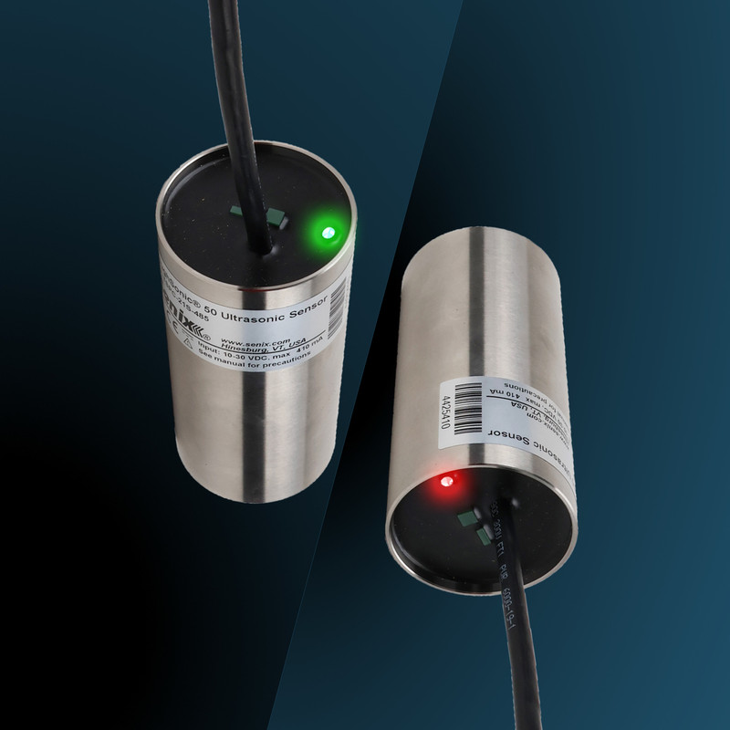
ToughSonic general-purpose sensors have a status LED that is green or red any time the sensor is powered.
Green means an echo was received on the last cycle. Red means no echo was received.
For Modbus polled data or ASCII streaming output, a distance measurement of 00000 signifies no echo was received. A time delay can be used before the analog or switch reaction occurs.
A switch that controls a valve or motor might activate incorrectly when the echo is lost. A way to monitor the presence or absence of target echo is recommended in this case.
The output levels or switch states are maintained in the response position for as long as the echo loss persists. This steady output might be missed or not interpreted as a no-echo response.
Senix recommends three methods to prevent oversight and ensure workers are aware of echo loss.
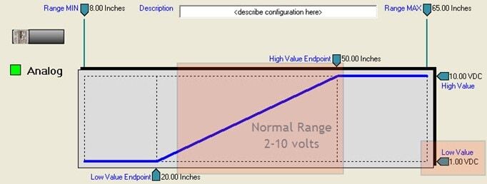
Set the analog range endpoints wider than the expected measurement range, and respond with a maximum or minimum value when loss of echo occurs—after an optional delay.
For Method #1, if the analog output may only reach a range of 6-18 mA normally, we recommend setting the “Loss of Target” response from 4-20 mA.
A PLC would be set to interpret that as a missing echo situation.
See an example below. After five seconds of no echo, the analog response to loss of echo is configured to go to the low value. The low value is outside of the normal analog range used.
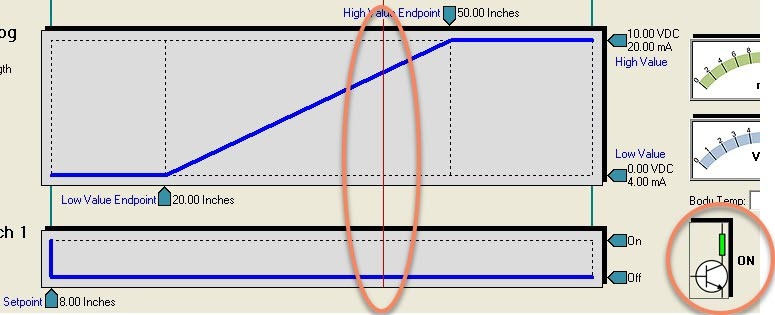
Set one switch to monitor over the whole operating range and configure it to react only to a loss of target echo—after an optional delay.
If the full 0-10 V or 4-20 mA range is needed, a switch is configured to respond only to a “Loss of Target” event. This is a handy feature to use while also taking analog 4-20 mA or 0-10 V from the sensor.
Configure it to either go to ON or OFF as appropriate upon a loss of target. The user knows the echo status independent of the other outputs, and they can use the switch to light an indicator.
Below is an example of Method #2. The full analog range is needed. The analog loss of echo response is to hold the last value, and a switch monitoring the echo goes ON after 10 seconds of no echo. This can be used to control an alert light.
The analog held the last value when echo was lost, while Switch #1 went active at loss.
Respond to a digital counts value of zero (000000) as a loss of target echo.