Address & Baud
Every sensor in the SYNC network must have its own network address within the range of 1-247 inclusive. All must use the same baud rate.
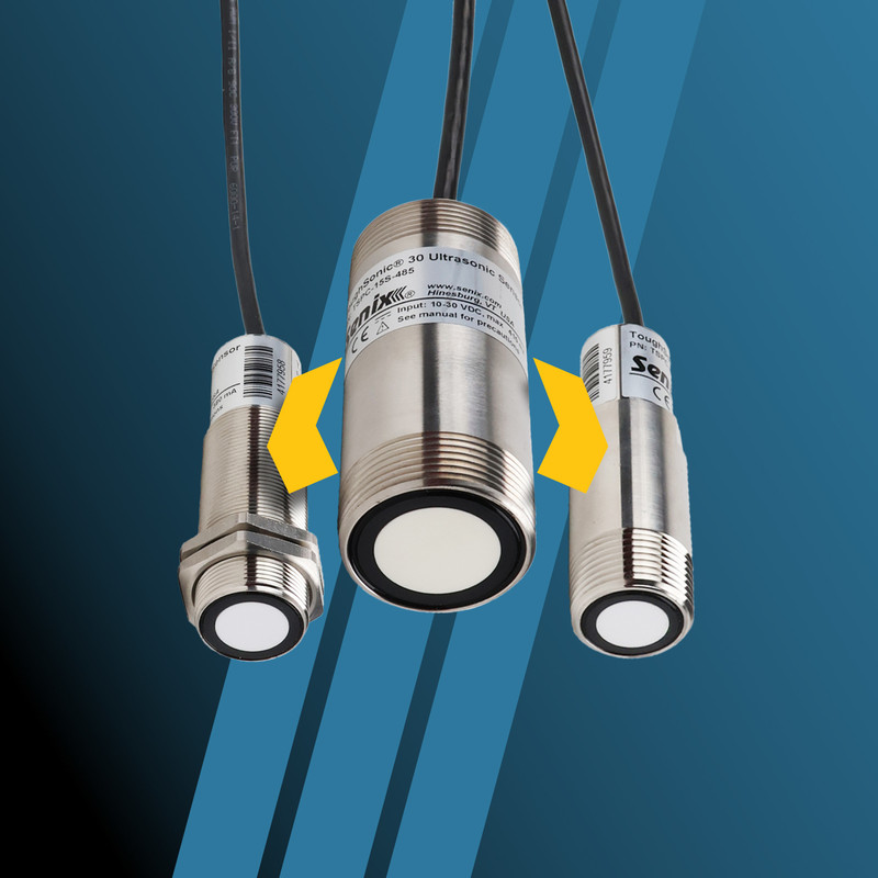
SensorView™ sensor configuration software allows up to 32 ToughSonic® sensors to be synchronized in a master-slave network.
In SensorView, SYNC mode is useful to prevent sensor interference from sensors located close to one another by alternating sensor measurement cycles.
It is also useful to acquire simultaneous measurements over an area using a grid of sensors that all measure at the same time. Greater precision can be obtained by using a higher baud rate than the default 9600 Baud—or communication data rate.
In SYNC, there can be up to 31 slaves organized in up to five phases with any number of sensors in each phase.
There can only be one master in a SYNC group; it measures on phase one.
The more phases in play, the slower the overall measurement function, since the master has to instruct all phases in succession. The interval value determines the rate at which the master controls the phases.
Additionally, SYNC networks operate on RS-485 communication protocol.
Since RS-232 does not support multi-addressable networking, RS-485 communication must be used to connect to a RS-232 sensor through SensorView.
Address & Baud
Every sensor in the SYNC network must have its own network address within the range of 1-247 inclusive. All must use the same baud rate.
Wiring Requirements
Sensors in an RS-485 network have their yellow and gray wires connected, or bussed. Additionally, all must share a common ground (blue) wire.
Reverting Sensors
All modified RS-232 sensors can be reverted to RS-232 configuration by use of the push button and TEACH command.
Determine which sensor will be the master; connect this sensor to SensorView
Determine the network address it will have; all new sensors default to “Address 1”
Under the menu item “Sensor,” choose “Communications" and assign a new address in the range of 1-247 inclusive
SensorView will disconnect and reconnect at the new address
Navigate to the “Measure” tool screen
Under “Measurement Activation,” choose the SYNC Master that matches the number of phases you intend to use. For example:
a. If you want all sensors firing at one time, choose “SYNC Master 1-Phase”
b. If you want your sensors grouped to measure in four groups, choose “SYNC Master 4-Phases”
c. If you want your sensors to measure in a repeating sequence, such as 123-123-123, choose “SYNC Master 3-Phase”
d. DO NOT choose a SYNC Master phase less than the number of phases you intend to have
Close the “Measurements” tool dialog. You will see a warning screen advising you that if you are connected to an RS-232 sensor, it is about to become RS-485, and you will lose the ability to communicate—unless you switch to RS-485 style interface equipment
a. This is why it is better to begin with all RS-485 sensors.
Disconnect the master sensor from SensorView
Connect the sensor that will become a SYNC slave using the proper equipment: RS-232 or RS-485, according to its label. The sensor should be the ONLY sensor on the network at this point.
Set its network address, as above
Choose its SYNC slave phase
Choose a different network address for each sensor. No duplicates are allowed
On the “Measurements” tool dialog, pull down “Measurement Activation” and choose the slave phase
Choose 1 if you want it to measure in phase 1 with the master
Choose 2—5 if you want it to measure at one of the alternate phases
Don't choose a phase number higher than the master phase number or it will not measure
Close the “Measurements” tool dialog. Observe the warning screen for RS-232 sensors
Disconnect the slave from SensorView. Remove sensor from the network
Repeat steps F—I for each slave. Remember: do not duplicate a network address
NOTE: At this point, every sensor must have a unique network ID and be set for the same baud rate.
Wire all network sensors together: this can be done by wiring between terminal boards with shielded twisted pair cable
Connect the slave sensors' gray wires together
Connect the slave sensors' yellow wires together
The blue reference (GND) must also be extended to every sensor
Connect the master’s gray, yellow, and blue wires to the network
Connect the PC to the network using RS-485 interface equipment
Make any regular analog output connections to external equipment as needed
NOTE: No serial data communication is possible using SensorView since the Master controls the bus.
Supply 15-30 VDC to every sensor
Once powered, all sensors will start measuring
Slave sensors are triggered by the master only
Analog and switch outputs are active while in SYNC mode
The SYNCed sensor group will operate in SYNC mode
While in SYNC mode, individual communication is not possible unless the “Master SYNC OFF” button is clicked—see the following section for more details
Open SensorView > Sensor > Group Control
In Group Control, click “Master SYNC OFF”
In the “Connect” dialog box, enter the network address of any sensor in the group
Click “Connect.” Import the sensor setup to the workspace when prompted
Make any changes to the sensor while in the workspace
Upload the workspace to the sensor by right-clicking the workspace icon and dragging it over to the sensor icon
NOTE: Only RS-485 sensors will be displayed. A slave sensor blinking red/green is not in communication with a master.
Open SensorView > Sensor > Group Control
Using RS-485 communication equipment, do a “Scan for Sensors” to display every sensor on the network and its address. Every sensor in the group should be displayed in the “Sensor List” area by address and configuration
If not, check wiring and review network addresses, as no duplicates are allowed
Click “Master SYNC ON” to restart the synchronized mode operation led by the SYNC Master
Stop SYNC operation, as above
Connect to the selected sensor using RS-485 communication equipment
Navigate to the "Measurements" dialog and choose “Continuous” from the Measurement Activation
Close the Measurements dialog and upload the Workspace to the sensor
NOTE: Any RS-232 sensor that had been automatically changed to RS-485 while in SYNC mode pull down menu will automatically revert to RS-232 at this time. It will communicate using RS-232 communication equipment.
On a push button model, use a TEACH-15 command
Unlock the TEACH mode by holding the button for three flashes and releasing
LED will flash slowly, indicating TEACH mode is invoked
Hold the button for 15 flashes, then release to cancel SYNC master or slave mode
Hold button for three flashes and release to stop TEACH mode. You can also cycle power, or simply wait 15 minutes
Any RS-232 sensor that had been automatically changed to RS-485 while in SYNC mode will *automatically revert to RS-232 after leaving SYNC mode. It will communicate using RS-232 communication equipment.
Remove any RS-232 sensor from the network. RS-232 only supports one sensor at a time.
Need further assistance with configuring your sensors or accessing SYNC mode? Contact the Senix team today.