Reference Target User Guide

Reference Target Temperature Compensation (RTTC) is an advanced temperature compensation for Senix’s ToughSonic® ultrasonic sensors.
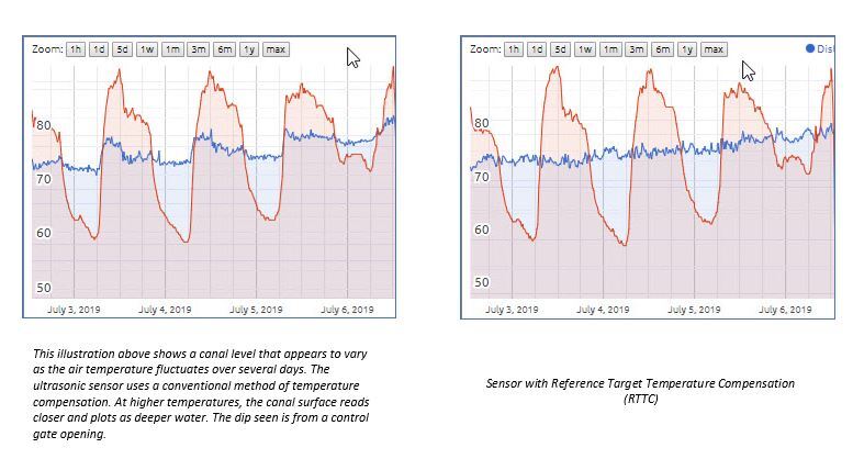
Ultrasonic sensors measure the time it takes to receive echoes from distant surfaces. When the air temperature changes, so does the speed of sound. This means a stationary surface appears closer or farther away when echoes are quicker or take longer to arrive.
Senix sensors have built-in temperature compensation. Compensation—done internally—can result in under- or over-compensation during times of rapid air temperature change, such as at sunup or when the sensor is warmed during the midday. RTTC overcomes that by measuring two targets for each cycle.
Target temperature compensation requires a reference target that is located in the sensor’s field of view and is unmoving. A closer reference target is used to adjust the measurement of the farther user’s target in real time. For example, here is a stream measured with internal temp compensation and with RTTC are illustrated for a 48-hour period:
Accessory targets are available from Senix for ToughSonic sensors with 30mm or 1” NPT threads. These targets can be used in the open, or the sensor can be mounted into a 2” NPT threaded riser, flange, stilling tube, or tank bung. RTTC works on serial-only, or serial plus analog and switch output sensors. RTTC is applicable to all Senix ultrasonic sensors.
Do not use Reference Target Temperature Compensation without a reference target installed, or the sensor will not perform correctly.
RTTC calibration can be done at any time, in any temperature within SensorView™ software. Read below for a step-by-step calibration guide.
Install and Prepare Reference Target Temperature Compensation for Use
- Install SensorView version 3.6.200 or higher to your PC (Available at Senix.com)
- In SensorView, upgrade the sensor firmware to version V47.fwu or higher.
- Install a Reference Target (RT) with thread adapter accessory to your 30mm or 1” NPT sensor. The target surface is the bent area at the tip. Do not alter the accessory by bending.
- Mount the sensor temporarily and point it to a wall or floor within range. The sensor can point horizontally or vertically for the calibration, but it should not shift.
You will need a tape measure to measure the true distance of a distant surface during the calibration. If the offset correction is not needed, no tape measurement is needed during calibration, and the sensor will deliver correct relative changes after calibration.
NOTE: The wall or floor test surface must be detected to calibrate RTTC.
- Power the sensor and connect it to SensorView. In sensor view, you should see a measurement of approximately 7 inches, which indicates the RT is being detected.
- Range MINIMUM must be less than 7” at this stage to see the RT
- If the distance shown is larger than 15”, the RT isn’t being detected. Nonetheless, if this is the case, you can still continue into calibration
- Make Range MINIMUM 15” by changing the “Range MIN” value in “Workspace” and uploading to “Sensor.” This blanks the RT from detection.
- The distance now shown should be approximately correct for the wall or floor surface the sensor is pointing at.
- The Echo Strength indicator should be about mid-range and blue. If the Echo Strength indicator is red, or the distance indicated is obviously incorrect:
- If Echo Strength is red—meaning no wall or floor surface is detected—click Workspace > Measure and choose “Free Air Medium” or “Free Air High.”
- Enable “Far Range Gain Boost.” Click OK and upload “Workspace” to “Sensor.” If the wall surface is detected, proceed to “Activation and Calibration” section.
- If Echo Strength is blue but weak, click Workspace > Measure > Advanced and change “Starting Gain” from 0 dB to 6 dB. Click OK, Exit, and upload “Workspace” to “Sensor.”
- Click Workspace > Measure and choose “Reference Target” in the “Temp Compensation” drop list.
- A “Reference Averaging” field will open, selected ON Click OK and move Workspace to Sensor
- A notice will appear, stating that making certain changes can affect the sensor’s calibration, so a fresh calibration should be considered if changes have been made.
- For first activation, a fresh calibration is required, and SensorView indicates 0.00 for a measurement.
- Two new boxes will appear on the “Sensor” view, one marked "R" and one marked "U." The R box will be RED at this stage.
- Two “Echo Strength” indicators will also now show. To the left is the RT strength, and on the right is U (user target) strength.
- To enter calibration, you must first be in “Sensor” view. In the “Sensor” drop menu, choose “Reference Target” calibration. A new dialog box opens for Cal Step #1 for the RT.
- An “Echo Strength” indicator should be green and a target distance should appear in the lower left window.
- If no RT is found, uncheck the “Limit Range” checkbox. If the target is outside a range of 6.00 to 8.00 inches, unchecking the box will allow it to be detected
- Be careful it isn’t detecting the far user target surface
- If no RT is seen, raise “Starting Gain” to 6dB or higher. Click Reset to refresh statistics windows
- Look for a small range, zero errors, and Std. Dev. of less than 0.004—these indicate a strong, steady RT. It is essential the RT is steady!
- If not steady, raise “Starting Gain” some more, click “Reset,” and note improvement
- When ready to continue, click “Go to Step 2” for the user target acquisition and offset
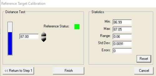
- Cal Step #2 shows the distant U target’s strength and stability. The “Echo Strength” indicator is much more active.
- Click “Reset” several times to let it settle. Look for a small range and Std. Dev., and zero errors. Use this image as a guide:
- Offset adjustment is optional for applications needing absolute distance, as well as relative change, in target position. Using a tape measure, measure the true distance to the wall or floor from the sensor face.
- Use the up and down arrows in the “Cal” window to adjust the distance value until it shows the true distance. Then use “Reset” to assist it to settle at the desired value
- When the true distance shows, the range is small, Std. Dev. is small, and there are zero errors, calibration is complete. Click “Finish.”
The “Sensor” view now has two green boxes marked "R" and "U." These indicate echoes are detected from both targets in each measurement. Echo Strength indicators also show both echoes in green.
If a reference target is lost, the “R” box goes red, and the sensor would use the last measurement of the reference target held in memory until the RTTC is restored. No temperature compensation is done when the R box is red.
Now that your RTTC is now active and calibrated, it will produce distance data without lagging compensation as air temperature changes. Its purpose is to give correct data of a variable liquid level or other target object, unaffected by warming of the sensor body or by rapid air temperature changes that occur when the sun rises or sets at a location.
To stop using RTTCT, go to Workspace > Measure > Temp Compensation and choose another compensation technique or choose “None.” Remove the RT from the sensor or increase Range MIN to blank and ignore the foreground reference target.
Repeat the calibration if the sensor is altered or replaced. Calibration can be done in the field, and at any temperature, using SensorView software and configuration. The only thing that is required is a tape measure—and only if absolute measurements are needed.
Otherwise, no offset correction is necessary, and the sensor will correctly show relative changes in position of the target object. Use the “Chart and Statistics tools” to review its stability.
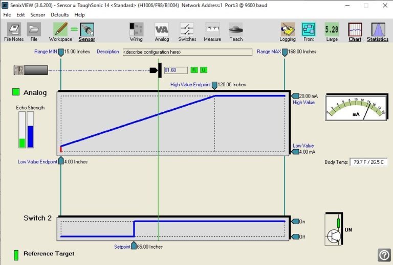
Check out this sensor view that’s showing RTTC active and with good echo indications. Setup also indicates a 4-20mA output, plus one switch output active, with the rectangular rear LED of the sensor set to indicate presence of the reference target.
Want more pointers on setting up and configuring your reference target? Contact the Senix team today.