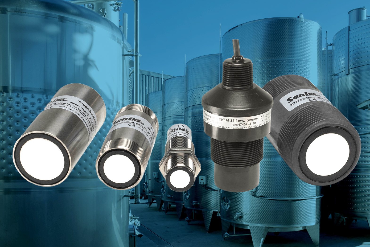
Setting an ultrasonic sensor up to measure in an enclosed space can be made difficult by factors such as greater distance, signal attenuation, air stratification, and temperature changes. Measuring dry materials brings special challenges due to the potential for sloping or slumping material, dust, and signal absorption due to material composition. To install a Senix sensor into a silo or bin over dry materials, several steps can maximize the chances of a successful application.

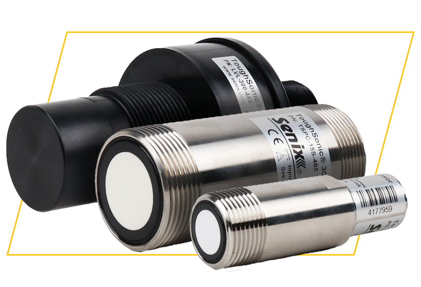
  • Choose the correct sensor. Senix sensor range specifications for hard surface and liquid targets must be de-rated 50% for use with porous, fibrous, powdery, or fine grained dry materials.  With that in mind, review the de-rated distance table below. The larger range sensors also operate at lower frequencies which aids difficult target detection at larger distances.
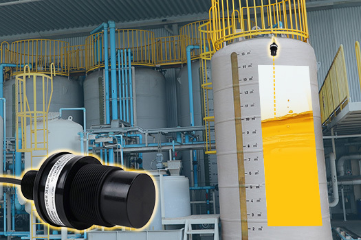
  • Mount and aim the sensor mindful of the application. Mount the sensor away from filling points or material falls. Don’t mount the sensor in the geometric center of the top. Remembering the sensor beam expands with distance at about 15 degrees, or about 25% of the distance, position the sensor away from pipes, ladders, struts, mixing blades, or other fixed or substantial objects. It may be a better choice to mount the sensor out of the vertical if it will be monitoring sloping surfaces.
  • Avoid acoustic coupling. The sensor should be de-coupled from the mounting surface by use of a plastic mount, or mounting in a shock absorbing clamp. Metal-to-metal contact, particularly if the sensor is mounted by threads close to the transducer, should be avoided.

Model

Range- Hard Surface or Liquid Range- Dry Materials

30S1

4” to 14 ft maximum 4” to 7 ft maximum
15S 10” to 30 ft maximum

10” to 15 ft maximum

21S and 25P 12” to 50 ft maximum

12” to 25 ft maximum


Setup Steps in Order

  • Set the operating range sufficient to reach the bottom. Running with a greater range than needed would allow time for multi-bounce echoes to arrive at the sensor in some circumstances, producing jitter or measurement errors. Set Range Maximum to the distance from sensor face to the lowest material level to be monitored plus 10%. This allows for temperature changes over a year’s time. Be aware of the sensor’s de-rated operating range.
    Use the Sensor Target Range Test in SenixVIEW on the Sensor pull-down menu once during initial setup. It can step through a test range in 1” slices to detect and evaluate potential targets. The test can be configured to concentrate on a small area to gauge relative strength of echoes too. If there are echoes from structures or tank wall welds for instance, the survey would be able to spot them. Re-positioning the sensor or smoothing the weld might allow the sensor to miss the offending object. Also use the Chart feature to evaluate echo quality at different operating ranges, defined with the Range Maximum and Minimum parameters.
  • For large silos or tanks use the Far Range Gain Boost feature found in the Measure tool dialog. If it’s missing, update your copy of SenixVIEW. This feature raises the sensitivity at the farther end of the range. Free Air Lo, Med, or Hi settings are more effective in the nearer portion of the measurement range. Stilling tube gain is linear and useful inside tubes or closed tanks where acoustic energy doesn’t dissipate fast. Start with higher gain and reduce until losses begin then raise slightly. Weak gain results in echo loss. Excessive gain may produce jitter.
  • Avoid short measurement intervals in closed spaces. Besides limiting the sensor range as indicated in the table below, running an interval too short may raise the acoustic energy inside the space to the point of interference. Slowing the sensor gives time for energy dissipation. Any sensor can interfere with itself if it runs too fast in an enclosed space.


Measurements per Second

Measurement Interval (msec) Approx. Max Range    inch (cm)

5

200 1080 (2743)

10

100

540 (1372)

20 50

288 (732)

40

25 144 (366)

100

10

54 (137)

200 5

24 (61)


  • With the range and gain set at starting values, set the power to 80% of maximum. If full range measurement can be achieved, lower the power by 5 over several trials each until you can’t maintain measurement of full range. Return the power setting up by 3—5. The power changes have more effect more in the lower half of the available range. Changing values have reduced effect when in the upper half of the range. Power and gain both affect jitter.
  • Filtering for stability. Filter choices depends on application. Input rejection (nearest of X, or farthest of X) allows location of the nearest or farthest reading within a sample set (generally 2—10 works well) and X of Y filters for a stable target; not usually practical for a silo. Averaging smooths changes if there are multiple jittery echoes due to marginal signals or high gain, but too high an average limits the rate of change of readings during rapid volume changes, something to avoid if the sensor output is used to control a valve or motor. Slew Rate also limits the rate of change. Don’t use slew rate generally in a dry materials environment, especially if sensor analog is used to drive control equipment unless the slew rate is set fairly large to react quickly. It can still be useful to calm sensor jitter however.
    Using multiple filters tends to slow the sensor output. Filters are applied in a sequence, input rejection followed by averaging followed by distance limiting. If multiple filters are used consider shortening the measurement interval to achieve a reasonable response rate.
  • Loss of Target Response: How the sensor responds to a loss of target is a consideration. Some customers want the analog output to run to one end. Others want the value to hold. For bin and silo installations where the distances or materials are more difficult there might be echo losses. Allowing the analog to make sudden large jumps is generally discouraged, so holding analog voltage and current values on loss of echo is used. Making use of a sensor’s switch outputs is one way to drive an alert circuit if the target echo is lost. Best approach is to allow for echo recovery and use a time delay of from seconds to minutes before changing a switch state. There is a delay input point associated with analog No Target settings as well as one in the Switches dialog box for use in conditioning switch states. On/Off delay differs from No Target Delay so be careful what you use.